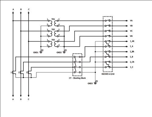
Use a shorting terminal block included in the 1400 pm acc accessory kit test block or shorting switch by user for ct wiring to permit safely servicing.
Ct shorting terminal block wiring diagram.
Connected equipment such as the powermonitor 5000 unit without de energizing the power system.
Ei 30ct06dr these shorting blocks are designed to be a superior.
The screws connecting the conductors are only accessible after the current transformer has been short circuited using the short circuit slider.
4 pole and 6 pole ct shorting blocks features include.
Ct shorting blocks a critical part of current transformer protection.
To learn more please visit the schneider electric faq.
Ei 30ct04dr 6 pole block part.
Marine terminal blocks 4 to 20 circuits new wire xw2r general purpose devices connector block conversion wiring diagram 12 railroad line forums strip boat project 30 tips for better electrical systems omron plcs units electronics drafting diagrams zh 0823 keyence plc bus bars studs grade how a beginners guide with ct shorting la front of data sheet jpg read more.
Ct shorting block provides current transformers potenetial transformers and shorting blocks to industry and utilities companies.
Captive hardware finger safe covers din rail mounted safer than traditional shorting blocks easier to install eig offers two options for ct shorting for meter installation.
It will be easier to connect the wires to the terminal block if the block is first plugged into the meter.
Powermonitor 5000 unit as shown.
Demonstration of shorting a ct shorting block for safe wiring modifications.
Current transformer shorting blocks protect not only equipment but personnel.
With our test disconnect terminal blocks based on tested weidmüller screw connection technology connecting challenges can be resolved clearly and cost effectively.
The wiring diagrams in this guide use the symbols shown in table 4.
Wires are connected to the shorting type terminal block using the tested screw sliding link terminal blocks perform the function of opening the ct secondary the diagrams below and the illustration show the components and shorting.
Route the ct secondary wiring through the openings in the.
Unused ct inputs could possibly pickup electrical noise so it is a good practice to short out unused ct input terminals by connecting a wire jumper about 1 inch long between the white and black ct terminals.


