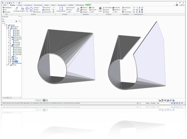
2 2 sheet metal conversion 2 2 1 ripping the shell in figure 2 does not yet represent a piece of bent sheet metal as it is not yet obvious which edges are folded and which are not continuous ripped.
Creo sheet metal shell.
First shell thickness defines flange size.
Select the create conversion feature the top icon to right of model screen and the smt.
Automate sheet metal design.
In the creation.
Just convert the imported 3d model into a creo sheet metal part by defining a driving surface and you re ready to go.
Convert a part to sheet metal.
In this tutorial we will learn about the basic techniques related to sheet metal functionality of creo parametric by modelling a cover.
Choose the method best suited to the design task by using a variety of modeling methods including 2d 3d idealized shell or.
First shell is made in solid part second shell is for conversion to sheet metal.
For this part i would use double shell method.
Using a variety of y and k factor bend allowance calculations designers can create flat patterns of the designs.
Download creo tutorials notes.
10 drafts shell holes 11 creating trajectory and profile ribs 12 creating blends and swept blends 13 relations parameters 14 surface modelling tools.
Creo cadds 5 sheet metal design option automates design and development of sheet metal components and folded plates including equipment chassis frames brackets and enclosures.
Conversion feature is used for edge rips and rip connects.
See convert a solid part into a sheet metal part for details.
When creating flat wall you have at corner of the bend line a white box which can be used for extending and.
Bend flatten cut and pattern par.
Now that you have a sheet metal part just go to the edit bend.
With creo s sheet metal design capabilities you can quickly and easily create walls bends punches notches and flanges.
With creo 4 now it s just as easy.


